LiPo Charging Circuit
Discovering a flaw in an example circuit design and fixing it.
The Exposition
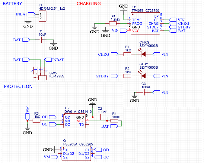
Back in the Spring semester of 2024, I attended an Advanced Prototyping course. The course focused on circuit design, 3D modeling, and high-fidelity fabrication through project-based learning. Example circuits were provided to take student’s attention off the finer details and focus on the prototyping process. Among these, was a circuit for charging a LiPo battery.

Figure 1: Example Circuit
LiPo batteries can be very tricky. Overcharge them, and they can explode. Underdischarge them, and they can stop working. Fortunately, there exist integrated circuits that can manage the fussy charging requirements and prevent over-discharging.
Our class charging circuit was designed around several such ICs:
- The TP4056, which charges the LiPo battery
- The DW01A, which prevents an over-discharge (among other things)
- Lastly, the FS8205A, a dual mosfet IC that the DW01A uses to disconnect the battery
Poking Around
Discontent with using the circuit as a black box, I started researching these three components to understand how they work. Forum posts on charging circuits were inconsistent, so I consulted the documentation for the ICs themselves and got familiar with the functions and pinouts of each.
Once I felt comfortable with the ICs, I started cross-referencing the example circuit with the datasheets to determine how they were connected, but something was off. I was unable to reconcile my knowledge of the ICs with the circuit example.
It was at this point that I started thinking that something was wrong. I double-checked the datasheets, but they were not complex, laying out very clearly the correct pinouts. I realized that something might have been wrong with the example circuit itself.
Something Wrong with the Example Circuit
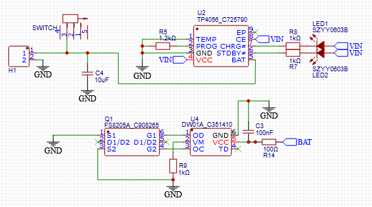
To start, I refactored the example circuit so I could figure out what was going on:

Figure 2: Refactored Example Circuit
After puzzling over it for a while, I realized what was confusing me. There was a design issue in the example circuit that was completely bypassing the DW01A, leaving the LiPo battery vulnerable to over-discharging!
Normally, the DW01A is supposed to work by sensing the voltage and current of the battery and disconnecting it if any one of many undesirable cases occurs. Many of these cases are redundant as the TP4056 can handle them itself, but in this circuit, the most important function that the DW01A handles is over-discharge protection. The DW01A doesn’t disconnect the battery directly, but instead sends signals to dual MOSETS (a kind of electrical switch) to disconnect the battery on its behalf.
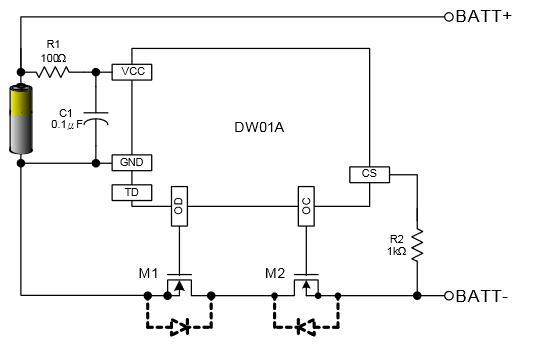
In the Typical Application Circuit, we can see how these two components should be wired to the battery:

Figure 3: Typical application circuit
In this diagram, the flow of current is being interrupted by the MOSFETS, meaning the DW01A can disconnect the battery when it needs to.
However, in Fig. 2, the refactored example circuit, the two sides of the dual MOSFET (labeled S1/S2) are not interrupting the current from the battery. They are in fact both connected to ground. If the DW01A decides the battery needs to be disconnected, turning off the MOSFETs will have zero effect. The load will still be connected to the battery through common ground.
This has the effect of:
- Causing longevity issues with the battery
- Making two ICs and a couple of components completely irrelevant
This kind of problem is very sneaky. When made into a PCB, the board appears to work fine. Any damage to the battery would only be noticeable long after the product is assembled.
Fixing the Issue
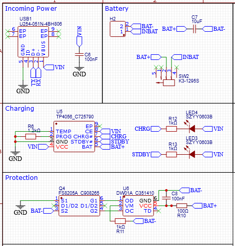
To solve this issue, I passed the negative side of the battery to common ground through the MOSFETS, following the typical application circuit. Some other reworking was required when components needed to be connected to the negative side of the battery instead of common ground, and vice versa. By the end, this was the circuit I ended up with:

Figure 4: Fixed circuit
Because of this simple change, the DW01A is able to do its job and the LiPo battery is protected from being over-discharged.
Outcome
Once I was sure my charging circuit was correct, I compiled my research and presented it to my professor. My professor was very receptive and is borrowing it for future classes. Unfortunately, we were too far into the semester to implement this change classwide, but I was able to incorporate it myself.
This is a good lesson about having a healthy skepticism toward technical sources and doing your own research. Evil bugs like this one are invisible if you’re not looking for them. This example circuit was being used for a long time because it came from a trusted source and was never thoroughly examined
I came out of the experience with a greater understanding of circuit design and a begrudging appreciation of technical documentation.